- Standard design constraints or Synopsys design constraints contains the timing and power related constraints which control design w.r.t to the spec.
- SDC contents:
#Clock definition:
To define clock, we need following four mandatory informations.
1. Clock source: it can be a port of the design or be a pin of a cell inside the design. (typically, that is part of a clock generation logic).
2. Period: the time period of the clock.
3. Duty cycle: the high duration (positive phase) and the low duration (negative phase).
4. Edge times: the times for the rising edge and the falling edge.
create_clock –name <clock_name> -period <Time_period> -waveform {<rise_time> <fall_time>} [get_ports <clock_port_name>]
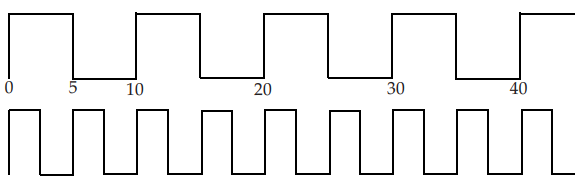
EG. -> create_clock –name test_clk -period 20 -waveform {0 10} [get_ports clk_pll]
create_clock –name test_clk -period 20 -waveform {10 20} [get_ports clk_pll]
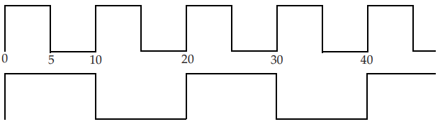
create_clock –name test_clk -period 15 -waveform {5 12} [get_ports clk_pll]
create_clock –name test_clk -period 20 -waveform {0 5 10 15} [get_ports clk_pll]
create_clock -period 1.2 -waveform {0.3 0.4 0.8 1.0} [get_ports clk_pll]
#Setting clock transition:
Set_clock_transition –rise 0.05 [get_clocks test_clock]
Set_clock_transition –fall 0.08 [get_clocks test_clock]
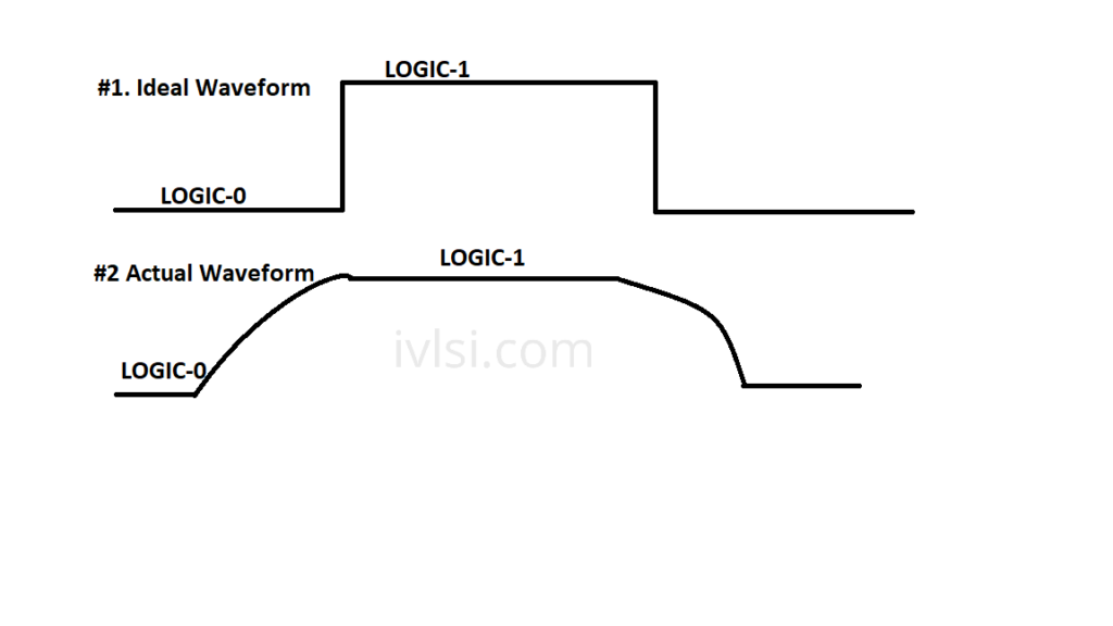 Setting Clock Transition[/caption]
#Clock Uncertainty:
set_clock_uncertainty -setup 0.01 [get_clocks CLK_CONFIG]
set_clock_uncertainty -hold 0.002 [get_clocks CLK_CONFIG]
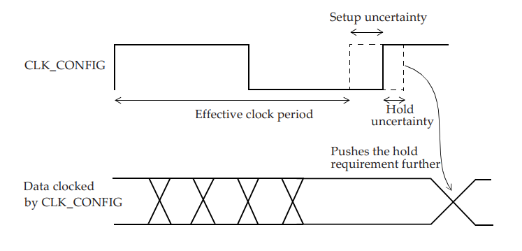 Clock Uncertainty[/caption]
#Interclock uncertainty:
set_clock_uncertainty -from SYS_CLK -to CFG_CLK -hold 0.05
set_clock_uncertainty -from SYS_CLK -to CFG_CLK -setup 0.1
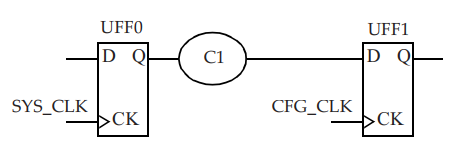 Interclock Uncertainty[/caption]
#Clock Latency:
set_clock_latency 1.2 -rise [get_clocks TEST_CLK]
set_clock_latency 1.8 -fall [all_clocks]
set_clock_latency 0.851 -source -min [get_clocks CFG_CLK]
set_clock_latency 1.322 -source -max [get_clocks CFG_CLK]
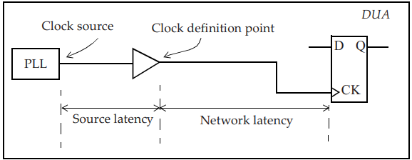 Clock Latency[/caption]
#Generated Clock:
There are two types of generated clocks:
#1. Divide By Clock
#2. Multiply By Clock
#1. Divide By Clock
create_generated_clock -name TEST_CLK_DIV2 -source TEST_PLL/CLKOUT -divide_by 2 [get_pins UFF0/Q]
#1. Multiply By Clock
create_generated_clock -name PCLKx2 -source [get_ports PCLK] -multiply_by 2 [get_pins UCLKMULTREG/Q]
 Multiply By Clock[/caption]
#Set input delay:
Set Tclk2q 0.5
Set Tc1 0.3
set_input_delay -clock CLKA -max [expr Tclk2q + Tc1] [get_ports INP1]
#Set Output Delay:
Set Tc2 0.5
Set Tsetup 0.3
set_output_delay -clock CLKQ -max [expr Tc2 + Tsetup] [get_ports OUTB]
Modeling of External Attributes, Mostly for IO path we need these attributes.
#set_drive
set_drive -rise 3 [all_inputs]
set_drive -fall 2 [all_inputs]
#set_driving_cell
set_driving_cell -lib_cell INV3 -library slow [get_ports INPB]
#set_input_transition
set_input_transition 0.85 [get_ports INPC]
set_input_transition 0.6 [all_inputs]
#set_load
set_load 5 [get_ports OUTX]
set_load 25 [all_outputs]
Four common commands that are used to constrain the analysis space are:
#set_case_analysis:
Specifies constant value on a pin of a cell, or on an input port.
set_case_analysis 0 [get_ports {testmode[3]}]
#set_disable_timing:
Breaks a timing arc of a cell.
set_disable_timing -from S -to Z [get_cells UMUX0]
#set_false_path:
Specifies paths that are not real which implies that these paths are not checked in STA.
#set_multicycle_path:
Specifies paths that can take longer than one clock cycle.