Integrated Clock Gating (ICG) Cell & Related Concepts
We always have target to close the design by meeting the PPA (Power, Performance, Area). Clock consumes most of the power as it has high switching activities. Being specific, clock consumes almost 20% to 40% of dynamic power. Even in the entire clock tree, 80% of the power is getting consumed by last stage of clock tree (Leaf cells and near about) from this 20% to 40%.
There are many ways to reduce the dynamic power and one of the ways which is used almost in every complex design is Integrated Clock Gating cells. Without clock gating, clock will be having very high activity and after using clock gating, we will see very less activity. Let’s discuss in detail what exactly is this cell, how where and when we use this cell, how this effects circuit. We will discuss about Timing calculations more in the timing section.
There are basically two types of clock gating cell:
- Clock gating using AND gate
- Clock gating using Integrated clock gating cell
Clock gating using AND gate
Normally, clock propagation is continuous process in the sequential elements even when there is no data at the data pin which we really don’t need. So to stop the clock when data is not there, we need some additional element which will control the clock propagation in a way so that when data is there clock propagates and clock stops when data is not there.
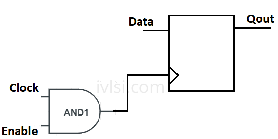
From the below circuit, we can see that the flip flop clock input is tied with a 2 input AND gate where one input is original signal and other is tied with Enable signal. We know the property of AND Gate is if both the inputs will be logic-1 then only output will be logic 1. Using this concept, we use the AND gate, if Enable signal is 1 then only clock will propagate. Using this method we save dynamic power by stopping clock transition when it is not required.
Clock gating using Integrated Clock Gating cell
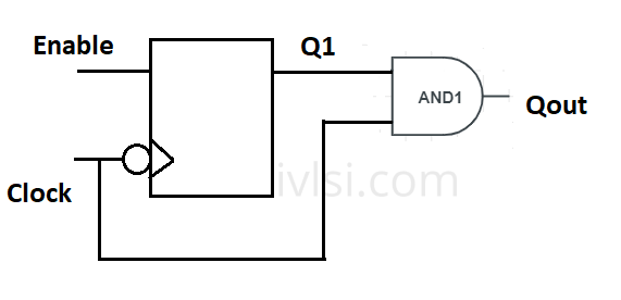
Now we know what our motive behind using the clock gating is. The problem with clock gating using AND gate is that the circuit might come with glitch. So to avoid this glitch, we need to have some solution. Here Integrated clock gating comes into picture. The integrated clock gating cell is made up of latch and AND cell. Let’s investigate the below circuit and understand.
Integrated clock gating cells use enable signal from the design. External signal also can control this. If we infer ICG cell before clock path, then a new circuit comes into picture and we can see a new timing path called as **clock gating path** group. We will discuss more about these in timing section. ICG is a must for all the low power designs as it saves a huge loss in terms of dynamic power.
Few more information on Integrated clock gating:
- Till final synthesis stage, ICG is not getting noticed.
- Timing violations are seen only after Clock Tree Synthesis.
- ICG cells are not skew balanced with the registers present.
- Half cycle path has been introduced which means timing available is less than cycle time.
- Mostly effects timing critical blocks.
- The best way to insert ICG cells are near to leaf cells of the clock tree.
- Clock enable input of the ICG should be generated in functionally related module or same module.
- ICG cells can be cloned if too many leaf cell groups are being driven by single ICG. One disadvantage of cloning is that the latency will get increased.