- The Design Exchange (DEF) file is an ASCII representation of physical information of the design.
- DEF contains Property definition, Die area, Row definition, Physical cell definition, STD cell definition, special net, regular nets, port, blockages, module constraints etc.
- Def File also contains physical informations but of designs (LEF contains info of cells and metal layers), the best thing is we can dump DEF at any stages of P&R like Floorplan, Place, CTS, Routing or even after ECO stages. Below is the detailed explanation of DEF file with comments.
VERSION 5.8 ; ## DEF version
DIVIDERCHAR “/” ; ##Divider char representation
BUSBITCHARS “[]” ; ## Bus bit char representation
DESIGN dummy design; ##Design Name (Partition Name)
UNITS DISTANCE MICRONS 4000; ##Unit definition
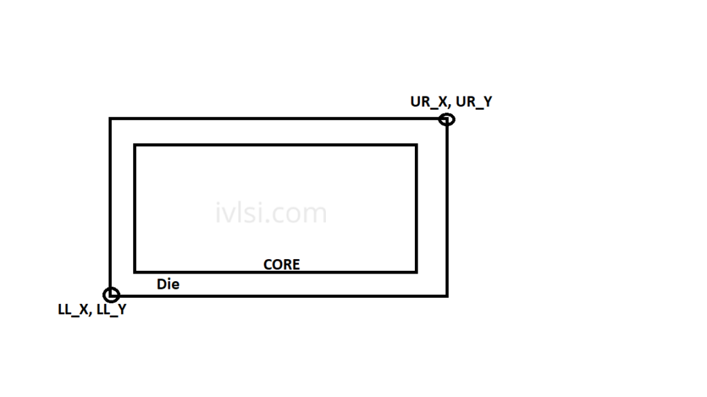
##Before going to next points lets understand the difference between die and core. Die area is total partition area but core area is where cells are being placed. Below picture explains well about die and core. I will explain this topic again in Floorplan as we need to deal with die and core during floorplan implementation.
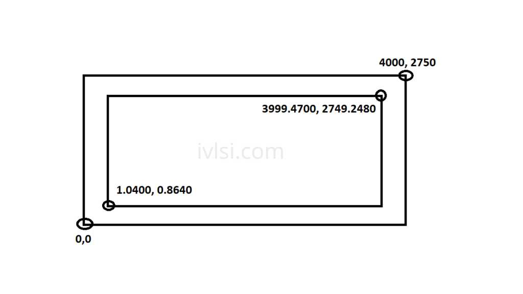
##Below property definition explains about the core bbox (Boundary Box), where LL_X is lower left of X coordinate, UR_X is upper right of X coordinate, LL_Y is lower left of Y coordinates, UR_Y is upper right Y coordinate.
PROPERTYDEFINITIONS
SPECIALNET wire_group_widest_stripe REAL ;
COMPONENTPIN designRuleWidth REAL ;
DESIGN FE_CORE_BOX_LL_X REAL 1.0400 ;
DESIGN FE_CORE_BOX_UR_X REAL 3999.4700 ;
DESIGN FE_CORE_BOX_LL_Y REAL 0.8640 ;
DESIGN FE_CORE_BOX_UR_Y REAL 2749.2480 ;
END PROPERTYDEFINITIONS
##Die area is defined as per below. Most of the designs in the industry nowadays are rectilinear, to understand how the floorplan is we can investigate the DIEAREA coordinates and accordingly we can find the actual shape of the partition. Let’s understand the below coordinates of Die and sketch the floorplan.
DIEAREA ( 0 0 ) ( 0 38 )
( 14 38 ) ( 14 22 )
( 18 22 ) ( 18 0 ) ;
## We will understand this after drawing the cordinates one by one with the help of below images.
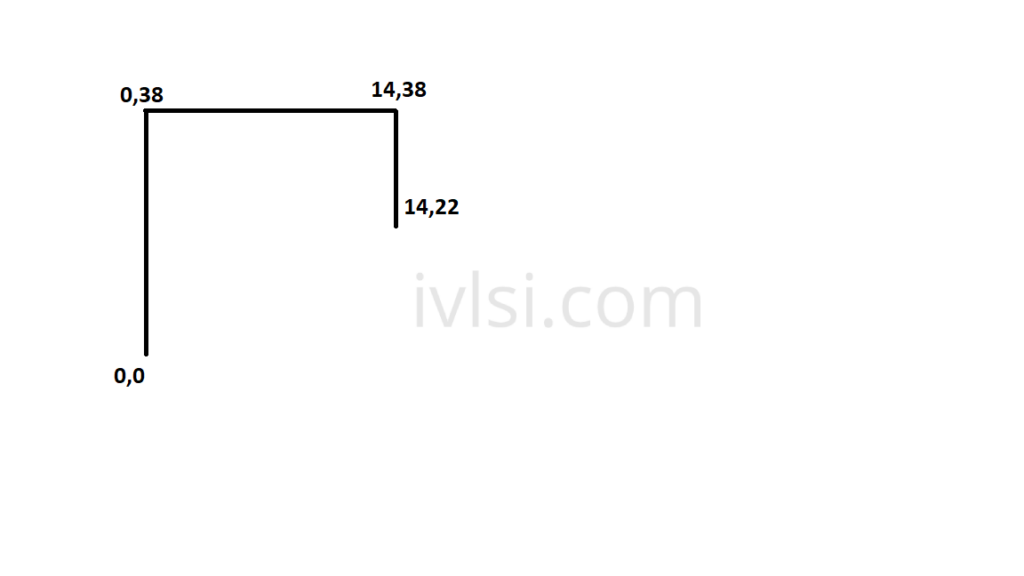
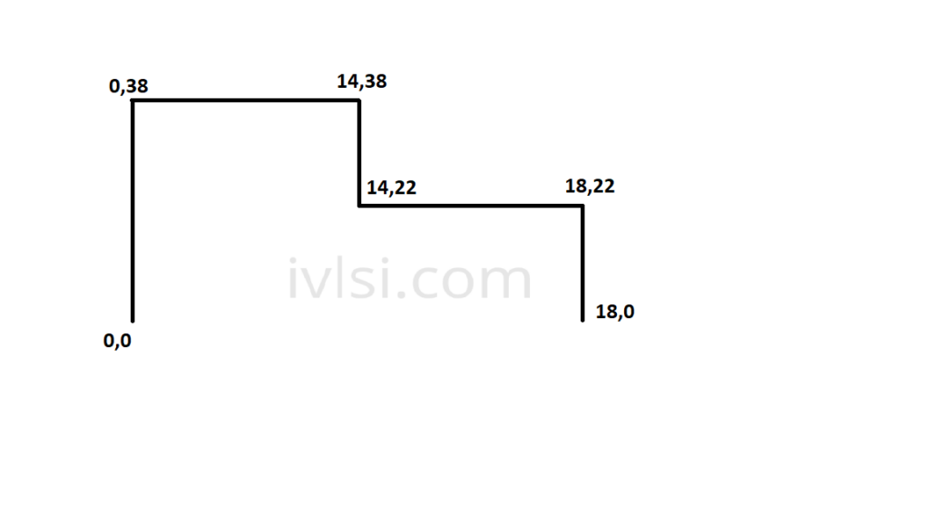
#1. Coordinates starts from (0,0) and goes to (0, 38) which means design starts from 0,0 and move to Y axis till it reaches the coordinate 38.

#2. Now second line getting started from (0,38) and ends at (14,38), which means Y coordinates not changing but x traverse 14 um in X direction. Look into the below image how the shape looks now.

#3. In the third coordinate we can see that x is constant but Y varies from 38um to 22um. Checkout below image which explains.
#4. Now coordinates changes from (14,22) to (18,22), which means it varies in X direction while Y is constant.
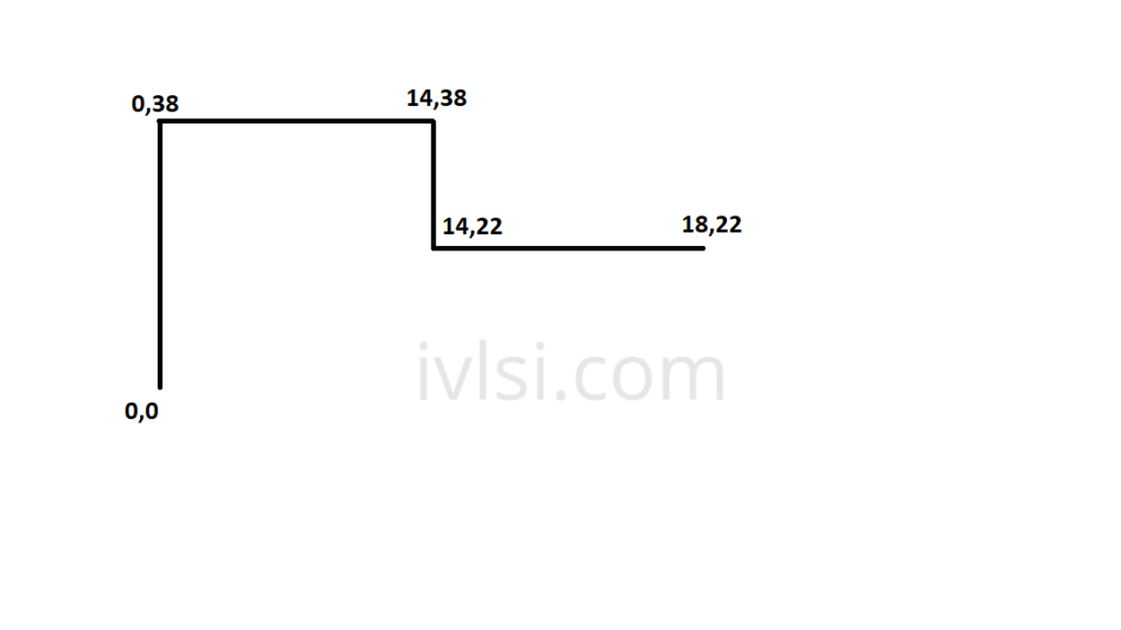
#5. At last one, Y traverses in a negative direction and meets at 0 again keeping X at 18 um. Below are the final images of the floorplan.
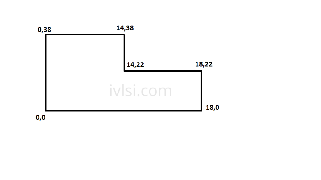
Final trace of the coordinates present in DIEAREA definition in DEF
Rows are defined as per below.
- ROW <ROW_NAME> <CORE_TYPE> <location> <Orientation>
E.g.
ROW CORE_ROW_0 UHDCORE 12594800 2725056 FS DO 2261 BY 1 STEP 216 0
ROW CORE_ROW_99 UHDCORE 14240720 2757024 N DO 211 BY 1 STEP 216 0
ENDCAP Cells are defined as per below.
- <Endcap_inst_name> <cell_name> <From_origin> <Status> <Location> <Orientation>
E.g.
ENDCAP_SS_20934 p0uhd_nn8_sec_hmvervss8x + SOURCE DIST + FIXED ( 12105560 5018976 ) N ;
ENDCAP_1285 p0uhd_nn8_sec_hmvervss8x + SOURCE DIST + FIXED ( 13061144 2807136 ) N ;
ENDCAP_17887 p0uhd_nt8_sec_plnl_edge_tie + SOURCE DIST + FIXED ( 15994640 5027616 ) FN ;
ENDCAP_17888 p0uhd_nt8_sec_plnl_edge_tie + SOURCE DIST + FIXED ( 15076640 5028480 ) FS ;
ENDCAP_17889 p0uhd_nt8_sec_plnl_edge_tie + SOURCE DIST + FIXED ( 15147056
Ports definition as per below in DEF.
PORT
+ LAYER M13 ( -936 -1266912 ) ( 936 1266912 )
+ FIXED ( 8806824 5149440 ) N
NEW D7 0 + SHAPE STRIPE ( 13908800 3001536 ) test_wrapper_S6_1x1_PG_opt2_uniq
NEW M2 0 + SHAPE FOLLOWPIN ( 8397920 5415552 ) test_wrapper_V1_1x1_PG_1T_uniq
STD Cells are defined as per below.
- <INST_NAME> <Cell_Name> <STATUS> <Co-ordinates> <Orientation>
U39591 r0hd_nn22_aoi22f01p00 + PLACED ( 995184 408288 ) S;
– U39592 r0hd_ln22_nr2rf01p33 + PLACED ( 986480 406608 ) FN ;
– U39594 r0hd_ln20_mxd2i1f02p00 + PLACED ( 811856 670368 ) FS ;
– U39595 r0hd_ln20_invrf02p00 + PLACED ( 808048 675408 ) N + MASKSHIFT 5
- Blockages are defined as per below.
BLOCKAGES 2936 ;
– PLACEMENT RECT ( 2112 772848 ) ( 687552 782928 ) ;
– PLACEMENT RECT ( 1483152 2232768 ) ( 1666752 2236128 ) ;
– PLACEMENT + SOFT RECT ( 341024 2316768 ) ( 365232 3869088 ) ;
– PLACEMENT + SOFT RECT ( 1666752 1622928 ) ( 1678992 2236128 ) ;
LAYER M2 + SPACING 0 RECT ( 880 3869840 ) ( 1484240 3870720 ) ;
– LAYER M2 + SPACING 0 RECT ( 1484240 2236880 ) ( 1485120 3870720 ) ;
END BLOCKAGES
- Special nets are defined as per below.
SPECIALNETS 237 ;
– vdd_cx ( * vdd_sub ) ( placeFE_OFC146634_i_llcc_retain_ff vdd_ext )
( placeFE_OFC145978_i_llcc_retain_ff vdd_ext ) ( placeFE_OFC145977_n vdd_ext )
( placeFE_OFC145976_i_llcc_retain_ff vdd_ext )
( placeFE_OFC146631_i_llcc_retain_ff vdd_ext )
END SPECIALNETS
NETS 582357 ;
– test_clk
( PIN test_clk ) ( placeFE_QC_EDI_flow_IoBufferC0_i_llcc_atb_clk a )
+ NONDEFAULTRULE NDR_M5M6M7M8_80w_100s_160p
+ USE CLOCK;
– test_ares
( PIN test_ares )
( u_llcc/u_llcc_perfmon/placeFE_QC_EDI_flow_IoBufferC1_i_llcc_atb_ares a ) ;
END NETS
- Instance Group/Module constraints are defined as per below.
GROUPS 29 ;
– u_lb/VDD_CX_INT
+ REGION u_lb/VDD_CX_INT ;
– u_mem_slp_pins/VDD_CX_INT
+ REGION u_mem_slp_pins/VDD_CX_INT ;
END GROUPS