What are Metal Layers?
- To route any PG/Clock/Signal we need metal layers. Metal layers connect the points of the two ends.
- There can be many numbers of metal layers which has been used to complete the routing. The number of metal layers to be used depend upon the foundry and technology node. Normally for 7nm TSMC technology node, 14 Metal layers are used and in 7nm Samsung technology node, 13 metal layers are used. There are as many metal layers present as it helps the design to converge more w.r.t to congestion.
- The metal layers are drawn in such a way that from M0-M14 we will have Horizontal and vertical metal layers. That means M0 is Horizontal, M1 is vertical, M2 is Horizontal, M3 is vertical and so on. The reason behind this horizontal and vertical gap is to make sure the metal layers routes are away from each other to avoid routing congestion, crosstalk etc. We will discuss these in detail in later sections.
- To connect with these metal layers, we need VIAs which connects two metal layers.
- Nowadays, Routing happens in 3-D stack.
- Resistance value decreases if we go further to higher metal layers. Normally M1 has 1.5 times higher resistance than M2, similarly M2 has 1.5 times higher resistance than M3 and so on.
- Let's understand the below picture to find out how metal is getting connected. If two points need to be connected, then tool will look for the shortest path and uses minimum layers to draw in order to achieve the target.
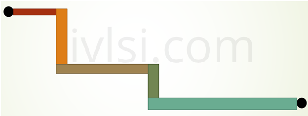
In the above figure, we can see that two points need to get connected through the different metal layers which is horizontal and vertical.