What is Signal Integrity and Crosstalk?
Let’s take one example. I am doing work from home in my study room attending meeting and my family is sitting in the TV room and watching some news. Even though I am sitting far, I can still hear the TV sound which is an extra unnecessary element for me. I don’t want to listen to this but still have to. This extra element is NOISE for me. In VLSI, we have same situation with the nets routed that even nets are at their track but impacted by the noise from other nets. This unwanted element is called Signal Integrity.
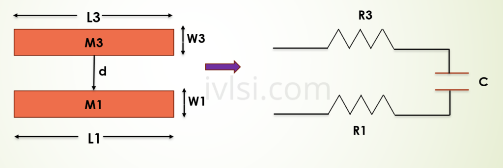
Signal integrity and crosstalk are quality checks of the clock routes. If we have crosstalk, then we might lose data or gain some extra data/logic which was not required. The below picture explains the RC extraction of 2 routed metal layers.
Types of Crosstalk
Basically, Crosstalk resulted into two major issue:
1. Functional Glitch
2. Timing variations
Reasons for Crosstalk
There are below reasons for crosstalk:
- Increasing number of metal layers
- Routing congested Design
- Thin and long metal layer routed
- Faster waveform due to higher frequencies
- Low voltage design
Fixes for Crosstalk
Practically we can get rid of the crosstalk using below methods:
- Upsize driver of the net having crosstalk
- Layer promotion for the net
- Apply NDR to those nets
- Shielding
- Break the long nets to avoid long traverse
- Aggressor downsizing
- Aggressor rip up
- Guard Ring