Macro Placement Guidelines
After pin placement, the next crucial step in physical design is macro placement. Proper macro placement ensures optimal routing, reduces congestion, and improves timing. Below are essential guidelines for macro placement that, if followed carefully, can help in handling complex blocks with ease.
Formula for Macro Spacing
Before placing macros, you can use the following formula to determine the required spacing between them:
📌 Distance between macros = (No. of Pins * pitch * 2) / Available Metal Layers
Key Macro Placement Guidelines
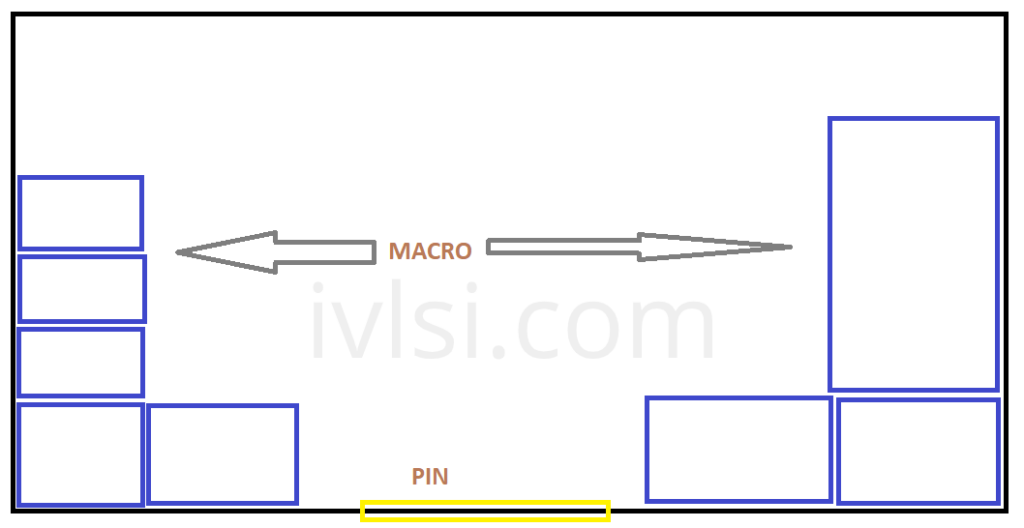
- Place macros at the periphery of the block.
- This ensures better routing access and reduces congestion inside the core.
- Logically related macros should be placed close to each other.
- This is known as logical grouping and minimizes long interconnect delays.
- Optimize channel width to avoid crisscross macro placement.
- Placement should align with track multiples to facilitate easier routing.
- Avoid placing macros or stacks near the ports.
- This prevents routing congestion in later physical design stages.
- Macro pins should face the core to reduce detours.
- This minimizes routing complexity and improves performance.
- Use a rectangular placement approach.
- Avoid irregular macro shapes to prevent area wastage.
- Create halos (keep-out zones) around macros.
- This helps to reduce congestion in surrounding areas.
- Use hard or partial blockages in gaps between macros.
- Prevents standard cells from being placed in congested areas.
- Avoid notches in macro placement.
- Ensures smooth routing and avoids unnecessary dead space.
- Maintain minimum gaps between macros.
- Helps in heat dissipation and avoids electromagnetic interference (EMI).
- Allow routing channels for buffer insertion.
- This helps in timing optimization and reduces congestion.
- Ensure macros are placed within their respective power domain fences.
- Helps in power integrity and isolation.
Pre-Placement Check: Fly Lines Analysis
🔍 Before placing macros, analyze the fly lines.
- Fly lines provide a visual representation of connectivity, guiding optimal macro placement.
- Helps in reducing routing detours and improving overall connectivity.
Conclusion
Macro placement is a critical step in physical design. By following these guidelines, you can achieve optimized routing, reduced congestion, and better performance for complex blocks. A well-placed macro setup ensures a smooth physical design flow while reducing iterations at later stages. 🚀