What is Floorplan?
Before hitting this particular topic of Floorplan, let’s take an example of building a house. If we are going to build a house, we first specify the area for different rooms, such as balcony, kitchen, lawn, etc. Similarly in case of building a chip, we first need to decide where we want to place different elements like pins, pads, standard cells, power pads, etc.
Now we need to decide the size/co-ordinates for these elements to be placed. If we are going to place the design size, then we take core or die as reference. Here we need to specify the aspect ratio, core utilization, cell utilization, dimension, the distance between the core and IO boundary, the distance between the core and die boundary, IO box calculation, floor-plan origin.
Import Design
Just before floorplan we need to import the design. Importing design means we need to feed all the required inputs into the physical design implementation tool to perform all the steps. We have already discussed the compulsory inputs in Physical Design Inputs module.
[caption id="attachment_562" align="aligncenter" width="1092"]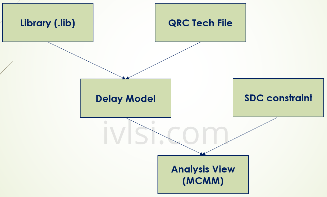 Floorplan Inputs in Physical Design VLSI[/caption]
In the above figure, we can see that with library (.lib) and Tech file, we create the Delay module. With delay model and SDC constraints, we create Analysis View where we create different corners named as Multi Mode Multi Corner (MMMC). In this corner we create Slow, Typical and Fast corners with Best, Typical and Worst mode for timing analysis.
By using all these data, we can decide which element should be placed.
Basic Floorplan
- ROWS: Rows are the locations where cells get placed. Rows can be core or IO. Rows are created at the floorplan stage.
- SITE: Sites are the minimum unit of placement. Rows are multiples of site definition. You can say that the smallest unit of placement where the smallest cell can be placed is called as SITE. This is technology dependent and obviously varies when technology changes.
- Floorplan is the process of deriving the die size, allocating space for soft blocks, planning power, and macro placement etc.
- We specify the floorplan by Size or Die/IO/Core Co-ordinates. We derive core and module sizes based on the standard cell utilization.
- Total density is calculated as:
Core Size= (standard cell area + macro area + halo) /standard cell utilization - Standard Cell Density is calculated as:
Core Size= (standard cell area/standard cell utilization) + macro area + halo
Benefit: Generates more accurate core and module sizes. - We define Core Size By or Die Size By, where core size by is defined by aspect ratio (Height/Width) and core utilization or dimension where we define height and width of core.
- We define core margin by Core to IO boundary or Core to Die boundary.
- Create physical shape of power domains which is defined in the UPF we have committed.
- Rows can be defined with different orientation as R0, MX, R0/MX Flip and abut, etc.
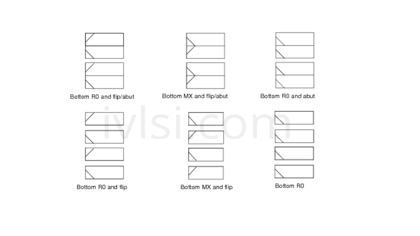 Macro Orientation in Floorplan[/caption]
Usually we chose Bottom MX and Flip/Abut in design these days, where Power/Ground (VDD/VSS) shared with up and down to avoid area loss. The notch we can see in the above figure is where Ground (VSS) will be inserted and will be shared by both sides of cells sitting UP and DOWN.
[caption id="attachment_570" align="alignnone" width="1072"] Site Rows in Floorplan[/caption]
In the above figure we can see that the first row belongs to VSS. This is because we don’t want to start from VDD as VDD from neighboring partition should not result into power loss (We will discuss this in later module).